
Hello everyone, in this article we will configure a standard access-list (ACL). We will build a small topology in Cisco Packet Tracer and walk through the configuration with practical examples.
First, what is an Access List (ACL)?
An access-list is a set of rules used to control traffic entering or leaving an interface on a router. As the name implies, it is a list of permit and deny statements that decide whether packets are allowed or blocked. ACLs are a fundamental security and traffic-control mechanism in Cisco IOS and other network devices. Before we apply any ACL rules, make sure basic routing is in place (in this lab we use static routes so networks can reach each other).
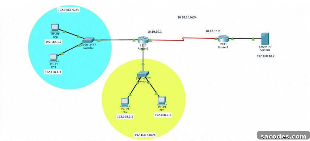
In the diagram above there are two different networks with distinct IP ranges and a single server. For our test, we want devices in the 192.168.2.0/24 network to reach the server, while devices in the 192.168.1.0/24 network should be prevented from accessing it. After configuring static routes on the routers, we will implement a standard ACL to enforce this policy.
Key best practice: standard ACLs filter only by source IP address, so they are typically applied close to the destination to avoid accidentally blocking entire networks from reaching other destinations. Extended ACLs, which can filter by source, destination, protocol and port, are usually applied close to the source. In this lab our destination is the server, so we place the ACL on Router1 near the server.
Below is the configuration used on Router1. These commands create a numbered standard ACL (number 10), permit all traffic from the 192.168.2.0 network, and deny all traffic from the 192.168.1.0 network. The wildcard mask 0.0.0.255 covers the entire /24 network.
Router1>enable
Router1#configure terminal
Router1(config)#access-list 10 permit 192.168.2.0 0.0.0.255
Router1(config)#access-list 10 deny 192.168.1.0 0.0.0.255
Creating the ACL entries is not sufficient by itself; you must apply the ACL to an interface and specify the direction (in or out). In our case we apply the ACL inbound on the serial interface that faces the networks:
Router1(config)#interface serial 0/3/0
Router1(config-if)#ip access-group 10 in
After this step, the router evaluates incoming packets on that interface using ACL 10. Remember that ACLs are evaluated top to bottom: the first matching permit or deny statement determines the fate of the packet. Also keep in mind there is an implicit “deny all” at the end of every ACL, so if no statements match, traffic will be dropped.
Additional practical notes and tips for working with standard ACLs in labs and production:
- Use clear, consistent numbering or named ACLs to keep configurations readable—numbered standard ACLs commonly use 1–99 (and expanded ranges such as 1300–1999) while extended ACLs use 100–199 (and expanded ranges such as 2000–2699).
- Verify ACL behavior with show commands, for example “show access-lists” or “show ip interface” to confirm the ACL is applied and to view hit counts for each statement.
- When designing ACLs, think about placement: standard ACLs are best placed close to the destination because they only filter on source address. Extended ACLs should be placed close to the source if you want to block unwanted traffic before it traverses the network.
- Avoid overly broad deny statements early in the ACL; order your statements from most specific to least specific when appropriate.
- In lab environments such as Packet Tracer, always confirm routing between networks first (static routes or a dynamic routing protocol) so ACLs test only access control, not connectivity issues.
In summary, we created a simple numbered standard ACL on Router1 to allow 192.168.2.0/24 to reach the server while denying 192.168.1.0/24. We applied the ACL inbound on the appropriate interface so the router enforces the policy. Remember to verify and monitor ACL hit counts and to design ACL placement carefully to avoid unintended traffic disruption.
Samed Gül